
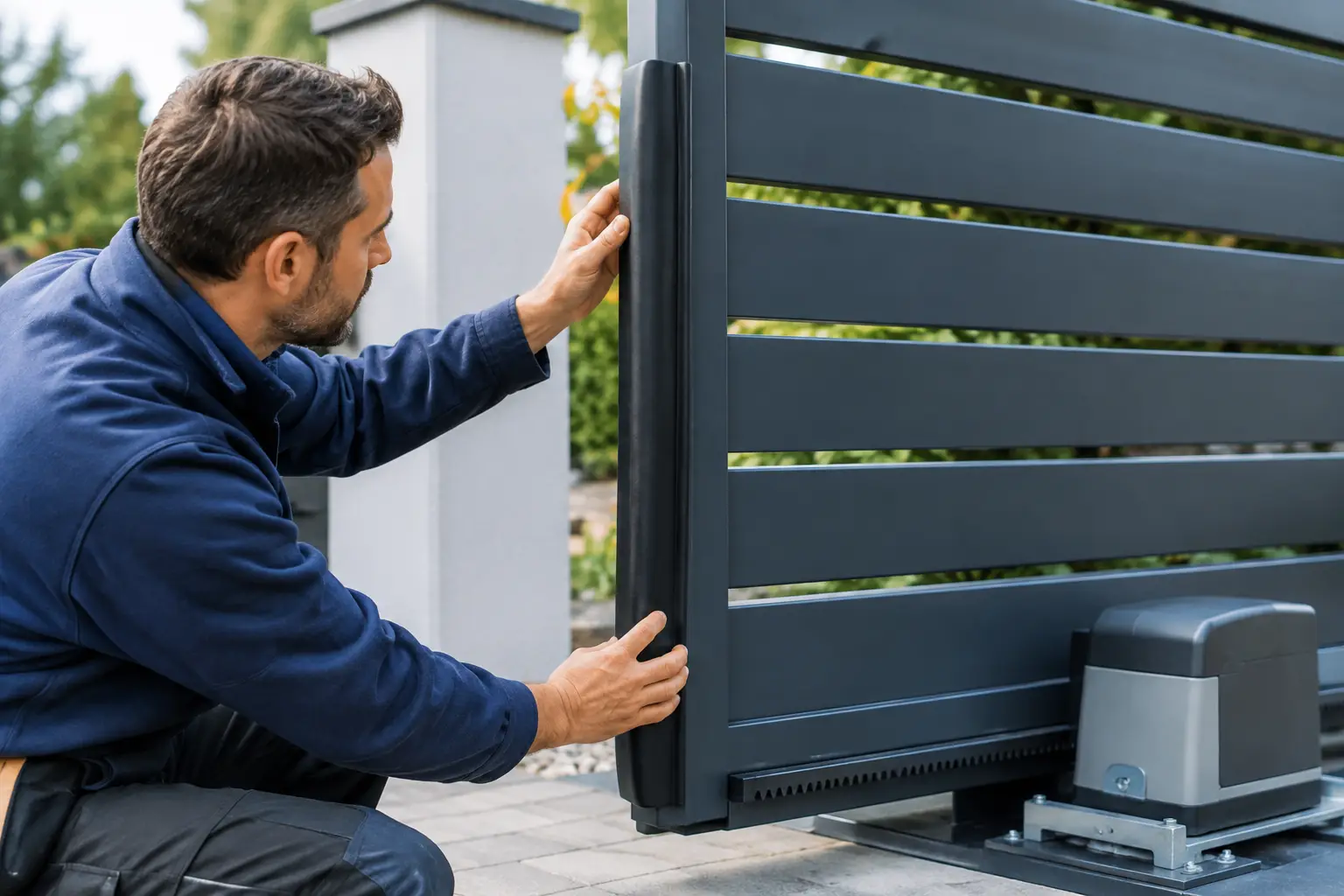
A gate can look and operate perfectly until it meets an obstruction. That is the moment its safety system matters. Knowing how to fit gate safety edges correctly is essential where an automated gate could trap, crush or shear against a post, wall, hinge area or gate leaf. The edge must be suited to the gate, connected to a compatible control panel and tested as part of the complete installation.
Safety edges are not an optional finishing touch. On many swing and sliding gate systems, they form a key part of the safety design alongside photocells, force limitation, warning devices and a proper site-specific risk assessment.
What a gate safety edge does
A safety edge is a pressure-sensitive strip fitted to a moving gate or a fixed surface within a risk area. When the rubber profile is compressed by a person, vehicle or object, it sends a signal to the gate controller. The controller should stop the gate and, where programmed and appropriate, reverse it.
They are commonly fitted to the leading edge of a sliding gate, the closing edge of a swing gate, and any point where movement creates a trapping risk. A closing gate leaf can create hazards at the hinge end, at the meeting point of two leaves, and between the gate and nearby masonry or fencing. The right protection depends on the arrangement on site.
A safety edge does not replace photocells. Photocells detect an obstruction before contact is made, while a safety edge responds when physical contact occurs. On a well-designed automated gate installation, the two systems often work together.
Assess the gate before fitting safety edges
Before selecting an edge or drilling a fixing hole, assess the whole gate movement. This should be done with the gate structure, automation and surrounding boundaries in mind, rather than treating the edge as a separate accessory.
Look at where the gate travels, closes and parks. Check for posts, brick piers, walls, railings, level changes and protruding gate furniture. Consider how pedestrians approach the entrance and whether children, visitors, delivery drivers or staff could come into contact with the gate. Commercial sites may also have regular vehicle movements, larger openings and different access arrangements to manage.
For sliding gates, pay particular attention to the main closing edge, the area between the gate and closing post, and any draw-in points around guides and rollers. For swing gates, consider the gap between leaves, the space behind an opening leaf, and pinch points close to the hinges or gate posts.
The gate type, its weight, operating speed and the control system all affect the final safety arrangement. A lightweight domestic gate with a low-energy operator is not assessed in the same way as a large commercial sliding gate. This is why a professional risk assessment is central to safe installation.
Choosing the correct safety edge
Most modern gate safety edges use a monitored system, commonly an 8.2 kOhm resistive configuration. This allows the control panel to identify not only an activation, but also a wiring fault or disconnected edge where the equipment is designed for monitored inputs.
Do not assume every edge will work with every controller. Check the automation manufacturer’s instructions and confirm whether the panel requires an 8.2 kOhm edge, a normally closed contact, or a specific interface. If the input and edge type do not match, the gate may fail to operate correctly or, more seriously, may not respond safely when the edge is pressed.
The profile also matters. A rounded rubber edge is often used on exposed leading edges, while other profiles are designed for mounting on a gate frame, post or flat surface. Choose a profile that covers the risk area fully and is durable enough for the gate’s environment. Gates exposed to coastal weather, regular vehicle use or heavy commercial traffic need particularly careful product selection and installation.
How to fit gate safety edges step by step
Isolate the gate system first
Switch off and isolate the electrical supply before working on the automation. Do not rely solely on a remote control or stop button. The gate must not be able to start unexpectedly while you are working on the leaf, cabling or control panel.
If the system has batteries or a backup supply, make sure these are isolated too. Electric gate systems should only be worked on by someone competent to carry out the electrical and automation work involved.
Mark the protected area
With the gate in its closed and open positions, mark the full length where the safety edge needs to sit. The edge should cover the part of the gate likely to make contact in the identified danger zone. Do not leave an unprotected section at the bottom simply because it is harder to fix – low-level areas can be especially relevant for feet, pets and small children.
Avoid fitting the edge where it will snag on the ground, catch a post or be damaged by normal gate travel. On uneven drives, check clearance across the complete path of movement rather than at one point only.
Cut and mount the carrier rail
Many safety-edge systems use an aluminium carrier rail fixed to the gate frame or protected surface. Measure carefully, cut the rail cleanly and remove sharp edges. The rail should be straight and securely fixed, with appropriate screws or fixings for the gate material.
On steel gates, take care not to compromise protective coatings unnecessarily. On timber gates, use fixings that will remain secure as the timber expands and contracts. For aluminium gates, use suitable fixings and avoid creating unnecessary corrosion risks between dissimilar metals.
Fit the carrier so that the rubber edge faces the direction of potential contact. Check that it does not interfere with gate stops, locks, catches or the operator arm.
Fit the rubber edge and end caps
Slide or press the safety-edge profile into the carrier rail in accordance with the manufacturer’s instructions. It should sit evenly without twists, stretching or gaps. Fit the supplied end caps and seals to protect the internal contacts from moisture and debris.
A poorly sealed edge can become unreliable over time, particularly on gates exposed to driving rain and road dirt. Take time to finish the ends properly rather than treating them as cosmetic details.
Route the cable safely
The cable route is one of the most important parts of fitting gate safety edges. A cable on a moving gate needs enough flexibility to travel without being pulled, crushed, rubbed through or trapped in the mechanism.
For swing gates, a protected flexible loop, travelling cable assembly or wireless safety-edge system may be appropriate depending on the layout. For sliding gates, the cable must be routed so it is protected throughout the gate travel. Keep all wiring clear of rollers, racks, hinges, sharp metal edges and areas where vehicles may damage it.
Use suitable external-rated cable and glands. Protect cables in conduit where needed, and leave enough controlled movement without creating a loose loop that can catch on the gate or ground. If using a wireless edge transmitter, ensure the receiver is compatible with the controller and that its battery condition can be checked as part of routine maintenance.
Connect and programme the control panel
Connect the safety edge to the designated safety input on the gate control panel, following the wiring diagram for that specific equipment. Do not bypass a monitored input with a link simply to make the gate run. A linked-out safety circuit may allow movement, but it removes the protection the system is intended to provide.
Programme the input according to the controller instructions. This may include selecting the edge type, setting its operating direction and configuring whether the gate stops or reverses after activation. The correct response depends on the gate design and the risk assessment.
Test the edge as part of the full safety system
Once the system is re-energised, test every safety edge individually. Apply firm, even pressure to several points along its length while the gate is moving in the relevant direction. Confirm that the gate stops and reverses, or stops, exactly as specified for that installation.
Then test the full system: photocells, manual release, safety edges, warning lights, control devices and the gate’s force settings. Repeat the checks with the gate opening and closing where applicable. A safety edge that works at one end but not another may indicate a wiring, alignment or profile issue.
Record the test results and show the property owner or site manager how the system operates. They should know not to use the gate if an edge is loose, damaged, permanently compressed or causing erratic operation.
When a professional installation is the sensible option
Fitting an edge may appear straightforward, but its effectiveness depends on the wider gate design, electrical connections and safety settings. Older installations can present additional problems, especially where controllers do not support monitored safety devices or where the gate itself has changed over time.
For domestic and commercial electric gates across Dorset and the South of England, Crabtree Electrical Gates can assess the hazards, specify suitable safety equipment and integrate it with the correct automation controls. This provides a safer result than adding a pressure strip without considering the gate’s full movement and use.
A safety edge should be checked routinely, not only when the gate develops a fault. If it is damaged, loose or fails a test, stop using the automated function until the issue has been properly investigated and repaired.
0 Comments